


There are about 195 hydrocracker units operating worldwide processing about 4,000,000 barrels per day (b/d), or about 550,000 metric tons per year (t/y) of feedstock. As of 2019, U.S. hydrocracker feedstock processing capacity was about 1,740, 000 b/d (238,000 t/y).
These units account for a multitude of proprietary designs, from single stage hydrocracker (either once through or with recycle) to multiple stage (typically two-stage) hydrocrackers.
Actual choice of configuration depends on regional economics of the individual refinery. For example, market conditions may be such that the unit is designed to run in VGO cracking mode in some cycles and in diesel/LCO treating mode in other cycles.
Hydrocracker design needs to be flexible because process objectives vary. For example, a facility with a large catalytic reformer may want to increase vol% of hydrocracked naphtha to the reformer.
Catalyst and reactor design have advanced to the point where hydrocracked naphtha sulfur content is near zero and can therefore be charged to the reformer without the need for hydrotreating, thus improving refinery efficiency.
Most hydrocrackers can achieve low sulfur or near-zero sulfur limits at start of run (SOR). For those refiners concerned that their unit may not meet sulfur specifications towards end of run (EOR), they have found it quite cost effective to install “appropriate” guard beds, such as a Ni guard bed or some other adsorbent type media with H2S trapping capacity. This can avoid having to process hydrocracker naphtha in a hydrotreater prior to reforming.
Single stage once through hydrocracking uses only one reactor and any uncracked residual hydrocarbon oil from the bottom of the reaction product fractionation tower is not recycled for further cracking.
For single stage hydrocracking, either the feedstock must first be hydrotreated to remove ammonia and hydrogen sulfide (H2S) or the catalyst used in the single reactor must be capable of both hydrotreating and hydrocracking.
Partly because of the effectiveness of new cobalt/molybdenum (Co/Mo) and nickel/molybdenum (Ni/Mo) catalysts, single stage hydrocracking with recycle is one of the most commonly used configurations. The uncracked residual hydrocarbon oil from the bottom of reaction product fractionation tower is recycled back into the single reactor for further cracking.
Two stage hydrocracker configurations use two reactors and the residual hydrocarbon oil from the bottom of reaction product fractionation tower is recycled back into the second reactor for further cracking. Since the first stage reactor accomplishes both hydrotreating and hydrocracking, the second stage reactor feed is virtually free of ammonia and H2S.
The high-boiling, high molecular weight hydrocarbon feedstock typically include vacuum gas oil (VGO). However, higher percentages of atmospheric gas oil, coker gas oil and LCO from FCC units are coprocessed through new and revamped units.
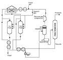
In any event, the gas oil feedstock is mixed with a stream of high-pressure hydrogen and then flows through a heat exchanger where it is heated by the hot effluent reaction products from the hydrocracker’s first stage reactor.
The feedstock is then heated further before it enters the top of the first stage reactor and flows downward through several beds of catalyst, with the first bed typically designed as a guard bed for demetallization, denitrification and desulfurization.
Temperature and pressure conditions in the first stage reactor depend upon the specific licensed hydrocracker design, feedstock properties, desired products, catalyst combinations and other variables. As a broad generality, the pressure in the first stage reactor may range from 35 to 200 bar and the temperature may range from 260 to 480 °C.
After the effluent reaction product stream from the reactor bottom is cooled by the incoming gas oil feedstock, it is injected with wash water, partially condensed in a water-cooled condenser and routed into a high-pressure vapor-liquid separator for separation into three phases: hydrogen-rich gas, hydrocarbon liquid and water.
Sulfur and nitrogen compounds in the gas oil feedstock are converted into gaseous H2S and ammonia by the hydrogenation that takes place in the first stage reactor. The purpose of the wash water is to dissolve some of the H2S and ammonia gases present in the first stage reaction product stream. The resulting aqueous solution of ammonium hydrosulfide (NH4HS) is referred to as sour water and is typically routed to a sour water stripper.
The hydrogen-rich gas from the high-pressure separator is routed through an amine scrubber where it is contacted with an aqueous amine solution to absorb and remove residual H2S in the gas.
The hydrocarbon liquid phase from the high-pressure separator flows through a pressure letdown (i.e., pressure reduction) valve and into a low-pressure separator. The reduction in pressure partially vaporizes the liquid. The hydrocracked endproducts of the hydrocarbon liquid phase from the low-pressure separator is heated and fed into the fractionator.
Not all of the feedstock hydrocarbons to the first stage reactor are hydrocracked (i.e., converted) into lower-boiling, lower molecular weight hydrocarbons. The bottom stream from the fractionator consists of the unconverted hydrocarbons from the first stage reactor and that stream is mixed with high pressure hydrogen and recycled as feed to the second stage reactor.
It is first heated by the hot effluent reaction products from the second stage reactor. The recycled feed is then heated further in a fuel-fired heater before it enters the top of second stage reactor and flows downward through several layers of catalyst. The temperature and pressure conditions in the second stage reactor depend upon the same variables as determine the conditions in the first stage reactor.
After the effluent reaction product stream from the second stage reactor bottom is cooled by the incoming recycle feed, it is partially condensed in a water-cooled condenser and routed into second high-pressure vapor-liquid separator for separation into two phases: hydrogen-rich gas and hydrocarbon.
To a large extent, the amount of hydrogen consumption in the hydrocracker reactors depends on the feedstock content of sulfur, nitrogen, olefins and aromatics. As a broad generality, the consumption of hydrogen in a hydrocracker may range from 1,000 to 3,000 standard cubic feet per barrel of feedstock. Quite a lot has been written as to the significant improvements in hydrocracker catalyst performance, and there are many. In the near future, continuous improvements to reactor internals, quench systems, recycle compressors, advanced fractionators controls and other related unit components will improve hydrocracker efficiency �)#
Leave a Reply
You must be logged in to post a comment.